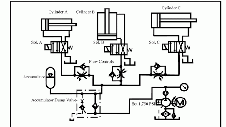
Pneumatic Actuation System Layout

Hydraulic Symbols Pneumatic Symbol Library Schematic Design Hydraulic Systems Engineering Symbols
Simplified Pneumatic Actuator Design And Operation Engineers Edge Www Engineersedge Com

How To Read Pneumatic Circuit Diagram Circuit And With Images Circuit Diagram Circuit Hydraulic Systems

Draw General Layout Of Pneumatic System And State Function Of Each Component In It
Chapter 5 Pneumatic And Hydraulic Systems Hydraulics Pneumatics

General Layout Hydraulic Pneumatic System

Understanding pneumatics is a matter of physics.
Pneumatic actuation system layout.

Image Result For Log Splitter Design Plans Log Splitter Wood Splitter Splitters

Plumbing System Controls Valves Valve Plumbing Valves Plumbing
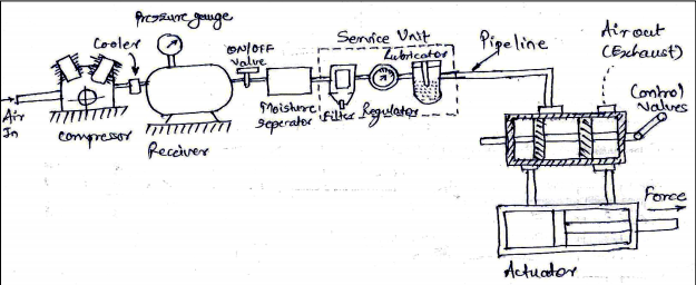
Draw A General Layout Of Pneumatic System And State The Function Of Components Topicwise Paper Solutions For Msbte

Nordyne Air Handler Wiring Diagram Fan Circuit Free For Ac Model E2eb 015ha 2 With E2eb 015ha Wiring Diagram Carrier Furnace Electric Furnace Thermostat Wiring
Source : pinterest.com
