Pneumatic Control System Sketch
The General Design Of A Pneumatic System And Its Components
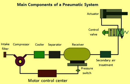
Basics Of Pneumatics And Pneumatic Systems Ispatguru
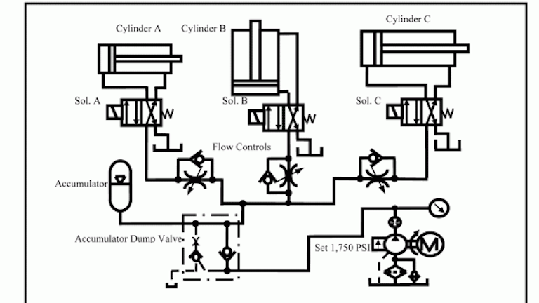
Chapter 5 Pneumatic And Hydraulic Systems Hydraulics Pneumatics
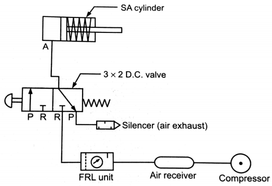
Explain Pneumatic Circuit For Speed Control Of Single Acting Cylinder With Neat Sketch Mechanical Engg Diploma Topicwise Notes And Solutions
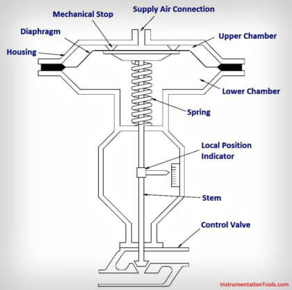
What Is A Pneumatic Actuator Instrumentationtools
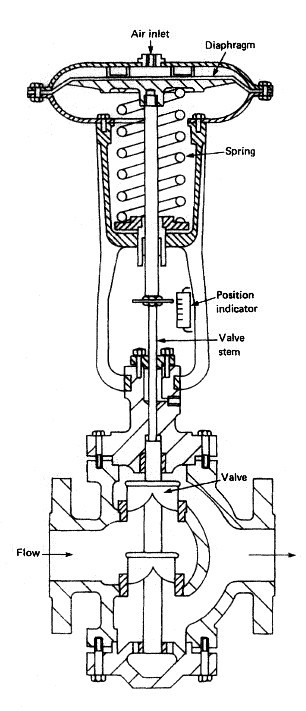
Pneumatic Control Valves For Marine Pneumatic Devices
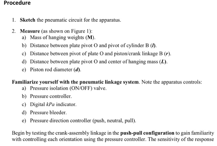
On off valve pneumatic sketch example double acting with a 5 2 solenoid valve two 3 2 air piloted pneumatic valves and a vessel air tank this sketch could apply to fail close or fail open valve.
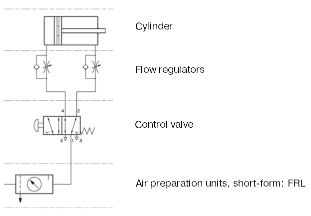
Pneumatic control system sketch.

Block Diagram Of The Pneumatic Actuating System 1 Download Scientific Diagram
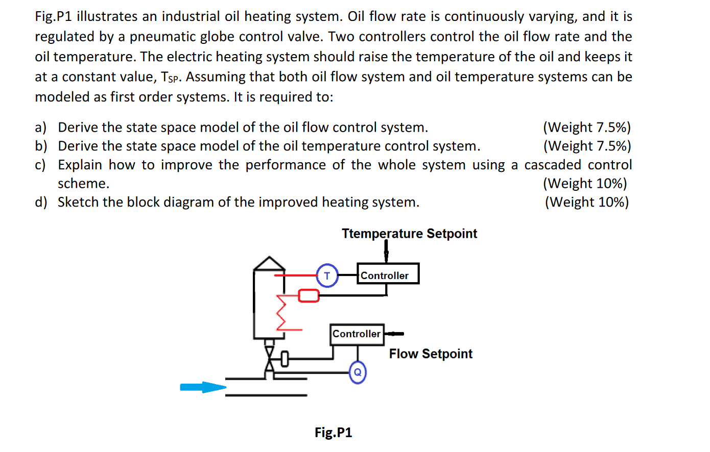
Fig P1 Illustrates An Industrial Oil Heating Syste Chegg Com
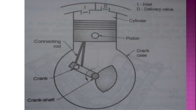
Pneumatic Control System
The Basic Components Of A Pneumatic System
Source : pinterest.com
